Viconics Thermostat User Manual: A Comprehensive Guide (Updated 12/11/2025)
Welcome! This manual provides detailed instructions for Viconics thermostats, including VT7600 and VT7225 series. Access online manuals at www.viconics.com for comprehensive support.
Viconics thermostats represent a commitment to advanced climate control solutions, designed for both residential and commercial applications. These programmable devices offer precise temperature management, enhancing comfort and energy efficiency. Understanding the core functionalities is key to maximizing their benefits.
This guide will walk you through installation, configuration, operation, and troubleshooting. Viconics prioritizes user-friendly interfaces alongside robust technological features. The VT7600 and VT7225 series, detailed within, showcase this dedication. Proper installation, referencing zoning system manuals, is crucial.
Furthermore, the manual remote control functionality, utilizing a momentarily closed contact, provides convenient adjustments. Remember to consult www.viconics.com for the latest updates and support resources. Addressing potential order delays, as outlined in document 028-0485-01_VT7225_EN, ensures a smooth experience.
Understanding Viconics Technology
Viconics thermostats leverage cutting-edge technology to deliver precise and reliable climate control. Central to their operation is the ability to link specific thermostats to designated channels, facilitating customized zoning and multi-unit management. The internal wiring, specifically the 24 VAC compressor stage 1 connection (T1), is fundamental to system integration.
The status display provides real-time information, crucial for monitoring performance and diagnosing potential issues. Temperature ranges are adjustable, offering increments of 5.0°F (2.5°C) or 1.0°F (0.5°C) for tailored comfort.
Viconics emphasizes seamless communication with the system, though errors can occur – troubleshooting guidance is provided later in this manual. Accessing online resources at www.viconics.com unlocks a wealth of technical details and support, ensuring optimal system functionality.
VT7600 Series Overview
The Viconics VT7600 series represents a programmable thermostat designed for advanced climate control. Installation begins with removing the security screw from the Terminal Equipment Controller cover – a crucial first step. The cover then aligns to the base and snaps securely into place from the bottom, ensuring proper enclosure.
These thermostats offer versatile scheduling capabilities, allowing users to customize temperature settings based on time of day and day of the week. The manual remote control function, activated by a momentarily closed contact, provides convenient override options.
For detailed installation guidance, refer to the complete installation manuals. Viconics Technologies Inc. provides comprehensive support through their website, www.viconics.com, and direct contact options.
VT7225 Series Overview
The Viconics VT7225 series thermostat is engineered for zoning system applications, demanding careful attention to wiring and installation procedures. Referencing the specific zoning system thermostat installation manuals is essential for complete information. Understanding the ‘Channel’ parameter is key, linking thermostats to specific Viconics functions.
This series features a clear status display, providing real-time information about the system’s operation. The manual remote control functionality, now utilizing a momentarily closed contact, offers convenient user adjustments. Be aware of potential order delays, detailed in document 028-0485-01_VT7225_EN, available at www.viconics.com.
Proper installation, as outlined in the manuals, ensures optimal performance and avoids operational issues.
Installation Procedures
Begin by removing the security screw from the Terminal Equipment Controller cover, then gently align and snap the cover into place, securing it properly.
Removing the Terminal Equipment Controller Cover
Before beginning, ensure power to the system is completely disconnected to prevent electrical shock. Locate the security screw on the bottom of the Terminal Equipment Controller cover. Using an appropriately sized screwdriver, carefully remove this screw and retain it for later re-installation.
Once the security screw is removed, gently grasp the cover and begin lifting it from the base. The cover is designed to snap into place, so a slight rocking motion may be necessary to release it. Avoid using excessive force, as this could damage the unit.
Lift the cover straight up and away from the base, exposing the internal wiring and components. Refer to Figure 3 for a visual guide. Caution: Be mindful of any connected wires as you remove the cover.
Aligning and Securing the Cover
After completing any necessary wiring or adjustments, carefully align the Terminal Equipment Controller cover with the base. Ensure the cover is oriented correctly, matching the contours of the base unit. Gently lower the cover onto the base, starting with the top edge.
Once aligned, press down firmly along the edges of the cover until you hear a distinct “snap;” This indicates that the cover is securely fastened to the base. Verify that the cover sits flush against the base, with no gaps or misalignment.
Important: Ensure all wires are neatly tucked away and not pinched between the cover and the base. Finally, reinstall the security screw on the bottom of the cover to prevent accidental removal and maintain safety.
Installing the Security Screw
Security is paramount. After aligning and securing the Terminal Equipment Controller cover, the final step is installing the security screw. Locate the designated screw hole on the bottom of the cover – this prevents unauthorized access and ensures the thermostat’s settings remain protected.
Using the appropriate screwdriver, carefully insert the security screw into the hole. Rotate the screwdriver clockwise until the screw is snug, but avoid over-tightening, which could damage the plastic housing. A firm, secure fit is sufficient to deter tampering.
Caution: Removing the security screw requires a compatible screwdriver. This feature is designed to prevent accidental adjustments or removal of the cover. Refer to Viconics Technologies Inc. at www.viconics.com for further assistance.
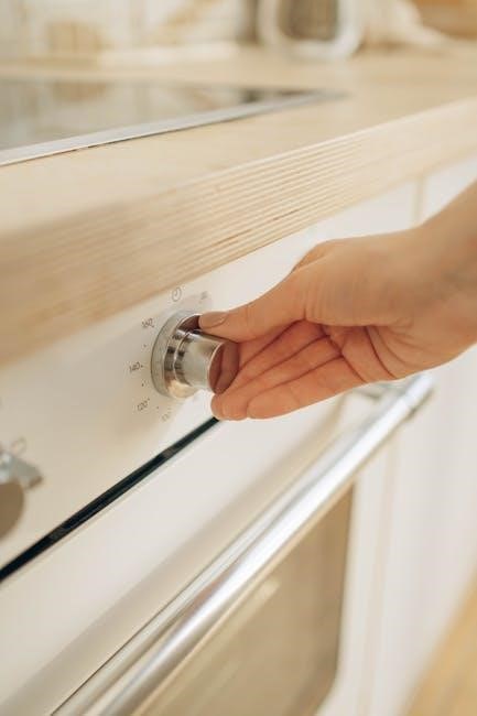
Thermostat Internal Wiring – Compressor Stage 1 (24 VAC)
Proper wiring is crucial for optimal performance. When connecting Compressor Stage 1 (24 VAC), carefully follow the wiring diagram provided in the complete installation manual. Incorrect connections can lead to system malfunction or damage.
Typically, the ‘T1’ terminal is designated for this connection. Ensure the wire is securely inserted into the terminal block, creating a reliable electrical contact. Double-check that the wire gauge is appropriate for the thermostat and system requirements.
Important: Always disconnect power to the system before performing any wiring. Refer to www.viconics.com for detailed wiring schematics and troubleshooting guides. Incorrect wiring voids the warranty.
Configuration and Status Display
Understand the status display for key information. The thermostat shows the displayed room temperature, ranging from 5.0°F (2.5°C) increments.
Understanding the Status Display
The Viconics thermostat’s status display provides crucial operational information at a glance. It clearly indicates the currently displayed room temperature, allowing for quick assessment of the environment. The temperature range is adjustable, offering both Fahrenheit and Celsius scales.
Specifically, the temperature can be adjusted in increments of 5.0°F or 2.5°C for larger adjustments, or more precisely with 1.0°F or 0.5°C increments. This flexibility ensures optimal comfort and control. The display also communicates system mode – whether in Heat, Cool, or Auto operation – and any active channel configuration for multi-thermostat setups.
Furthermore, error messages or system alerts will appear on the display, providing immediate notification of potential issues. Refer to the troubleshooting section of this manual for detailed explanations of these codes. Regularly monitoring the status display is key to efficient operation.
Temperature Range and Increments (Fahrenheit & Celsius)
Viconics thermostats offer versatile temperature control, supporting both Fahrenheit (°F) and Celsius (°C) scales to suit user preference. The displayed room temperature range is broad, accommodating diverse climate conditions. Users can customize temperature adjustments with selectable increments for precise comfort.
For larger adjustments, increments of 5.0°F (2.5°C) are available, while finer control is achieved with 1.0°F (0.5°C) increments. This dual-increment system allows for both quick temperature shifts and subtle fine-tuning. The selected scale and increment are easily configurable through the thermostat’s settings menu.
Accurate temperature readings are essential for efficient heating and cooling. Viconics ensures reliable performance within the specified range, providing consistent comfort. Refer to the configuration section for detailed instructions on changing temperature scales and increments.
Channel Configuration for Multiple Thermostats
Viconics systems support multiple thermostats, each requiring unique channel configuration for proper operation. This parameter, often referred to as “Channel,” is crucial for linking specific thermostats to corresponding functions within the Viconics control system. Correct channel assignment ensures that each thermostat independently manages its designated zone or area.
The channel configuration process involves assigning a unique numerical value to each thermostat during initial setup. This value identifies the thermostat to the system, enabling targeted control and monitoring; Improper channel configuration can lead to communication errors or unintended control actions.
The manual remote control function is now controlled by a momentarily closed contact. Refer to the system documentation for detailed instructions on channel assignment and troubleshooting potential communication issues.
Manual Remote Control Functionality
Viconics thermostats offer a manual remote control function, providing users with a convenient way to override programmed settings temporarily. This functionality is particularly useful for immediate adjustments to temperature or fan operation without altering the established schedule. The system now utilizes a momentarily closed contact for remote control activation.
To engage the manual remote control, a brief activation of the designated input is required. This signal instructs the thermostat to operate according to the remote setting until either a programmed schedule resumes or the remote control is deactivated.
Ensure the wiring for the remote control input is correct, referencing the installation manuals for specific wiring diagrams. Proper configuration guarantees reliable operation and prevents unintended system behavior.

Operating Instructions
Viconics thermostats allow easy temperature setting, schedule programming, fan control, and system mode selection (Heat, Cool, Auto) for optimal comfort.
Setting the Temperature
Adjusting the temperature on your Viconics thermostat is straightforward. The displayed room temperature range is 5.0°F, with increments of 1.0°F (or 2.5°C and 0.5°C, respectively, when in Celsius mode). To modify the setpoint, utilize the up and down arrow buttons located on the thermostat’s interface.
Pressing the up arrow will increase the desired temperature, while the down arrow will decrease it. The thermostat will immediately display the new setpoint. Ensure the selected temperature aligns with your comfort preferences and energy-saving goals. Remember that the thermostat responds to momentary closed contact for manual remote control.
The system will then work to achieve and maintain this temperature, providing consistent and comfortable heating or cooling as needed. Regularly check the displayed temperature to ensure it reflects your desired setting.
Programming Schedules
Viconics thermostats offer robust scheduling capabilities to optimize comfort and energy efficiency. While specific programming steps vary by model (VT7600, VT7225), the core principle involves defining different temperature setpoints for various times of the day and days of the week.
Access the scheduling menu through the thermostat’s interface. You can typically create multiple periods per day – for example, ‘Wake,’ ‘Leave,’ ‘Return,’ and ‘Sleep’ – each with a unique temperature setting. Carefully consider your daily routines when establishing these schedules.
Refer to the complete installation manuals for detailed, step-by-step instructions. Proper scheduling can significantly reduce energy consumption and enhance overall comfort. Remember to save your changes after programming!
Fan Control Options
Viconics thermostats provide several fan control options to enhance your comfort and indoor air quality. The ‘Auto’ setting operates the fan only during heating or cooling cycles, conserving energy. The ‘On’ setting keeps the fan running continuously, providing consistent air circulation and potentially improving air filtration.
Some models may offer a ‘Circulate’ mode, which periodically runs the fan for a set duration, even when heating or cooling isn’t active. This helps maintain even temperatures throughout your space. The manual remote control functionality can also influence fan operation.
Consult your specific VT7600 or VT7225 installation manual for detailed instructions on accessing and configuring these fan control settings. Proper fan control optimizes both comfort and energy efficiency.
System Mode Selection (Heat, Cool, Auto)
Viconics thermostats offer three primary system modes: Heat, Cool, and Auto. Selecting ‘Heat’ mode activates the heating system when the room temperature falls below the setpoint. ‘Cool’ mode activates the cooling system when the temperature rises above the setpoint. The ‘Auto’ mode intelligently switches between heating and cooling to maintain your desired temperature, optimizing comfort and energy use.
The specific method for switching between these modes varies depending on your VT7600 or VT7225 model. Refer to your installation manual for detailed instructions. Ensure the correct mode is selected for optimal system performance.
Incorrect mode selection can lead to inefficient operation or discomfort. Understanding these options is crucial for maximizing your Viconics thermostat’s capabilities.
Troubleshooting Common Issues
Common problems include power failures, inaccurate readings, and communication errors. Consult this section for solutions, or visit www.viconics.com for support.
Thermostat Not Powering On
If your Viconics thermostat fails to power on, begin by verifying the power supply to the terminal equipment controller. Ensure the security screw is properly installed, as removal can interrupt the electrical connection. Double-check all wiring connections, specifically the 24 VAC power source, confirming secure and correct placement.
Inspect the fuse (if applicable) within the system and replace it if blown. A lack of power can also stem from issues with the connected HVAC system itself. If the problem persists, consult the zoning system thermostat installation manuals for additional troubleshooting steps related to wiring configurations. Remember to disconnect power before inspecting any wiring. For further assistance, contact Viconics Technologies Inc. at the details provided in the Resources and Support section.
Incorrect Temperature Readings
If your Viconics thermostat displays inaccurate temperature readings, first confirm the selected temperature scale (Fahrenheit or Celsius) is correct. The thermostat offers a range of 5.0°F with 1.0°F increments (or 2.5°C with 0.5°C increments). Ensure the thermostat isn’t exposed to direct sunlight, drafts, or other heat sources that could influence the sensor.
Verify proper airflow around the thermostat. If the issue continues, recalibrate the temperature sensor following the procedures outlined in the complete installation manual available at www.viconics.com. Consider potential interference from nearby electronic devices. If discrepancies persist, contact Viconics Technologies Inc. for expert support and further diagnostic guidance.
Communication Errors with the System
Experiencing communication errors? First, verify the thermostat’s wiring connections, ensuring they are secure and match the wiring diagram in your installation manual. Confirm the system’s power supply is stable and within the specified voltage range. Check the channel configuration, as each thermostat must be uniquely assigned a channel for proper system integration.
If using multiple thermostats, ensure there are no channel conflicts. Refer to the zoning system thermostat installation manuals for detailed wiring and configuration information. For persistent issues, consult the Viconics Technologies Inc. website (www.viconics.com) or contact their support team for assistance. Document 028-0485-01_VT7225_EN may also provide relevant troubleshooting steps.
Fan Not Responding
If your fan isn’t responding, begin by verifying the fan control settings within the thermostat’s configuration. Ensure the system mode is set to a function requiring fan operation (Heat, Cool, or Auto). Inspect the thermostat’s internal wiring, specifically the connections for the fan relay, ensuring they are secure and correctly installed according to the wiring diagram.
Confirm the system’s power supply to the fan is active. Check for tripped breakers or blown fuses. Referencing the zoning system thermostat installation manuals can provide specific wiring guidance. If the issue persists, contact Viconics Technologies Inc. at their listed telephone, fax, or toll-free number, or visit www.viconics.com for support resources.
Safety and Maintenance
Prioritize safety! Always disconnect power before cleaning. Gently clean the thermostat. Replace batteries (if applicable) to ensure optimal performance and longevity.
General Safety Precautions
Important Safety Information: Before commencing any installation or maintenance procedures on your Viconics thermostat, always disconnect the power supply to the heating and cooling system at the breaker panel. Failure to do so could result in electrical shock or damage to the equipment.
Ensure that all wiring connections are secure and comply with local electrical codes. Do not attempt to repair the thermostat yourself; contact a qualified technician for assistance. Keep the thermostat dry and avoid exposing it to extreme temperatures or humidity.
This device is intended for indoor use only. Do not use abrasive cleaners or solvents when cleaning the thermostat, as they may damage the surface. Always follow the manufacturer’s instructions and safety guidelines to ensure safe and reliable operation. Improper installation or use may void the warranty.

Cleaning the Thermostat
Maintaining a Clean Thermostat: To ensure optimal performance and longevity of your Viconics thermostat, regular cleaning is recommended. Before cleaning, always disconnect power to the system at the breaker to prevent electrical hazards.
Use a soft, dry cloth to gently wipe the thermostat’s surface. Avoid using water, abrasive cleaners, or solvents, as these can damage the display or casing. For stubborn dirt or fingerprints, lightly dampen the cloth with a mild soap solution, ensuring it is wrung out thoroughly before use.
Do not spray any liquids directly onto the thermostat. Carefully clean around the buttons and display screen. After cleaning, dry the thermostat completely before restoring power. Regular dusting will help prevent buildup and maintain a clear display.
Battery Replacement (If Applicable)
Battery Powered Operation: Certain Viconics thermostat models may utilize batteries for backup or primary power. If your thermostat displays a low battery indicator, or ceases to function correctly even with power supplied, replacement is necessary.
Consult your specific model’s documentation to identify the correct battery type and quantity required. Typically, this involves removing the thermostat cover (after disconnecting power!) and locating the battery compartment. Carefully remove the old batteries, observing the correct polarity (+ and -) markings.
Insert new batteries of the specified type, ensuring correct alignment. Replace the battery compartment cover and reattach the thermostat cover. Verify proper operation after battery replacement. Dispose of old batteries responsibly, following local regulations.

Resources and Support
Viconics offers extensive support! Visit www.viconics.com for online manuals. Contact them via Tel, Fax, or Toll Free for assistance with your thermostat.
Accessing Online Manuals (www.viconics.com)
Viconics provides a comprehensive library of resources directly accessible through their official website, www.viconics.com. This online portal serves as a central hub for all thermostat-related documentation, including detailed user manuals for the VT7600 and VT7225 series, as well as installation guides and troubleshooting tips.
Users can easily navigate the site to find specific information pertaining to their thermostat model. The website also hosts important documents like the instructions regarding order delays (Document 028-0485-01_VT7225_EN). Furthermore, referencing the zoning system thermostat installation manuals is crucial for complete wiring and installation details.
Regularly checking www.viconics.com ensures you have the latest updates and support materials for your Viconics system, maximizing its performance and longevity;
Contacting Viconics Technologies Inc. (Tel, Fax, Toll Free)
For direct assistance with your Viconics thermostat, or if you require clarification beyond the online manuals, Viconics Technologies Inc. offers multiple contact methods. Their dedicated support team is equipped to address a wide range of inquiries, from installation questions regarding models like the VT7600 and VT7225, to troubleshooting common issues and understanding specific system configurations.
You can reach Viconics via telephone, fax, or their toll-free number. While specific contact details aren’t provided here, visiting www.viconics.com will provide the most current information. Ensure you have your thermostat model number readily available when contacting support to expedite the assistance process.
Prompt and efficient support is a cornerstone of the Viconics customer experience.
Referencing Zoning System Thermostat Installation Manuals
When integrating Viconics thermostats, particularly within a zoned heating or cooling system, it’s crucial to consult the dedicated installation manuals for those specific zoning components. The Viconics thermostat manual provides general guidance, but detailed wiring diagrams and configuration specifics are found in the zoning system documentation.
These supplementary manuals outline the necessary connections between the Viconics thermostat (such as VT7600 or VT7225 series) and the zone control panel. They detail proper wiring procedures, ensuring seamless communication and optimal system performance. Ignoring these resources can lead to incorrect installation, system malfunctions, or voided warranties.
Always prioritize referencing the complete set of instructions for a fully functional setup.
Understanding Order Delays and Instructions (Document 028-0485-01_VT7225_EN)
Viconics Technologies Inc. acknowledges potential order delays and emphasizes the importance of carefully reviewing Document 028-0485-01_VT7225_EN, available at www.viconics.com. This document details specific procedures to mitigate confusion and expedite processing. Accurate order information is paramount to avoid setbacks.
The document outlines required specifications, including model numbers (like VT7225), quantities, and shipping details. Failure to adhere to these instructions can result in significant delays or incorrect shipments. Please ensure all provided data aligns with your purchase requirements.
Proactive review of this document ensures a smoother transaction and timely delivery of your Viconics thermostat.